Case Study: SLA 3D printed Linear Gear for Extensometer


With this article we carry on with our series of posts with real-life SLA 3D printing cases. This article will cover all steps of producing SLA 3D printed linear gear up until the final result and is also dedicated to new users as well as experienced ones.
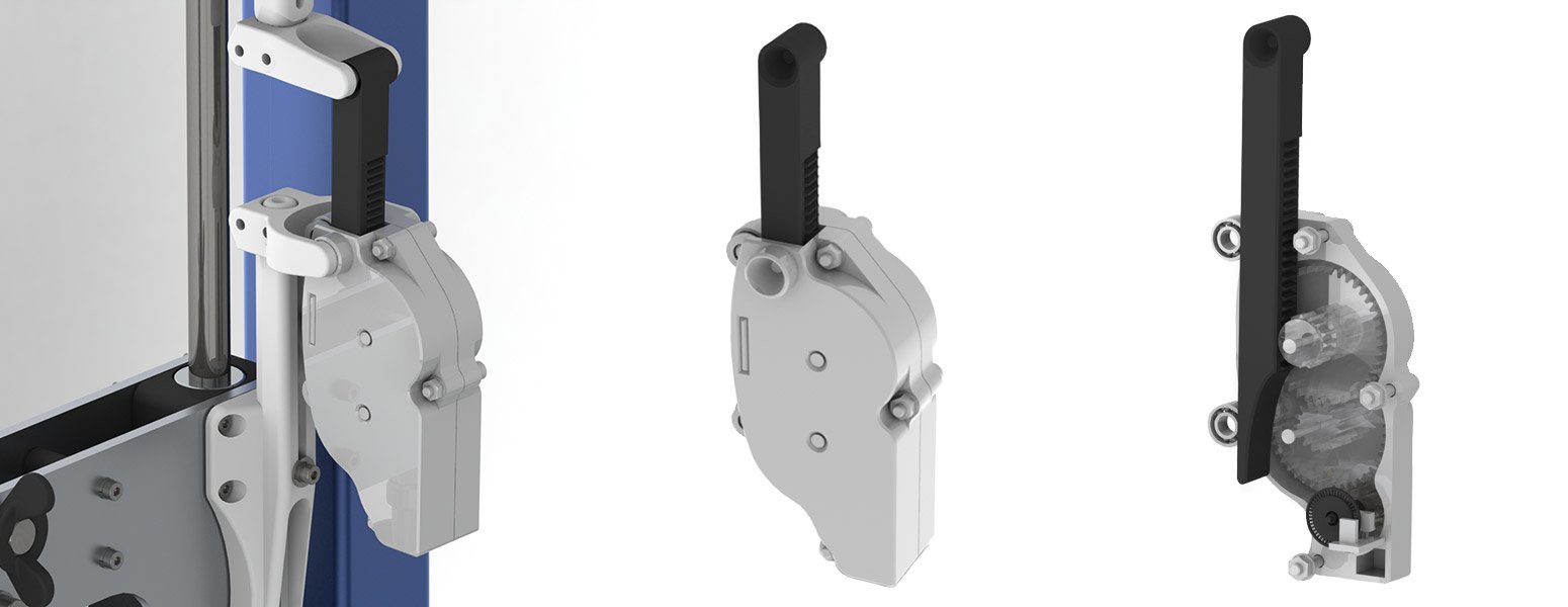
This case covers remarkably interesting part for even more interesting device. Our friends from nearby makerspace decided to build their own extensometer for various scientific purposes. The plan was to 3D print an entire device and make everything from scavenged equipment. We will come back to other parts of this instrument in the future. Now we will analyze, how to 3D print its key part – linear gear.
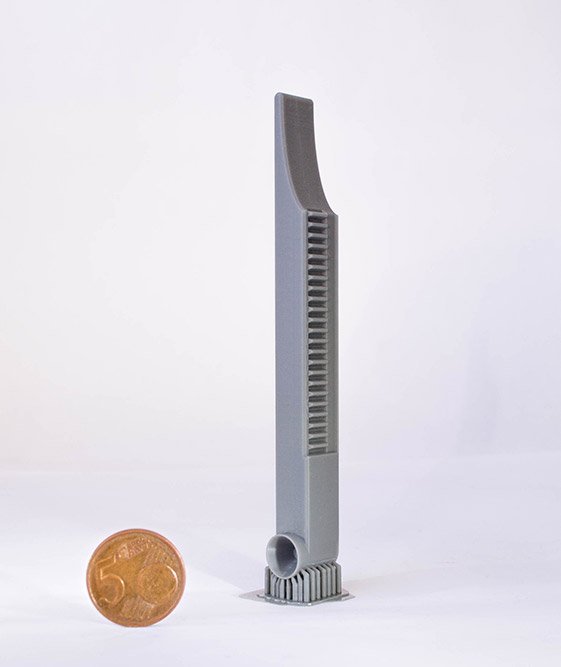
The purpose of this 3D printed linear gear is quite simple. It turns linear movement, i.e. in this case extension of something, into rotational movement. To measure the change in angular position or motion and calculate extension, we use classic rotary encoder scavenged from an old mechanical mouse. Do not be deceived by a simple design, because this system is able to measure changes with an accuracy of 50 um. Remember, that everything is 3D printed here!
Analysis
This linear gear, although, looking simple, is quite tricky to produce. To obtain desired resolution and accuracy we need extreme surface smoothness. Apart from surface quality, we also need to obtain dimensions as precisely as possible. The only 3D printing technology that would help us achieve all of that is resin 3D printing.
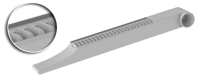
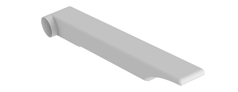
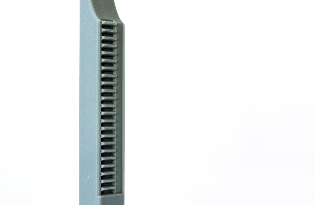
This part has a lot of functional and important surfaces. Front part with teeth is critical, because it turns linear movement into rotational and works together with gears. This front surface must be extremely precise and smooth to avoid potential measurement inaccuracies.
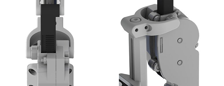
Sides of linear gear must also be as smooth as possible, because the whole gear is placed in “U” shaped trough that is located at the back of the extensometer. Any bumps and irregularities on sides might cause issues and inaccuracies during the vertical movement.
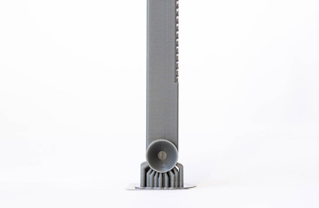
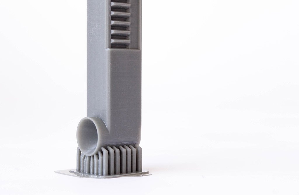
Finally, back side of the linear gear is also important. Ball bearings at the back hold the linear gear in place vertically and move together. Any irregularities can cause uneven vertical position. This will eventually result in potential inaccuracies and inconsistent data.
Therefore, all these sides cannot have support marks as that will cause potential issues during movement.
Due to high requirements for surface quality, we decided to 3D print this gear at 50 um layer height as that will produce desired surface quality. Thicker layers like 100 um might bring undesired unevenness. On the other hand, thinner layers like 25 um will dramatically increase 3D printing duration.
There are some requirements for 3D printing material as well. This linear gear must be very hard, and no flexibility is desired for this application. In other words, it must be as solid as a rock. Our chosen material must also have extremely low shrinkage profile. This is mandatory to obtain and sustain correct dimensions. This part will not be coated, so it must keep geometrical stability while ambient UV light is present. We decided to use AmeraLabs AMD-3 LED resin.
Orientation
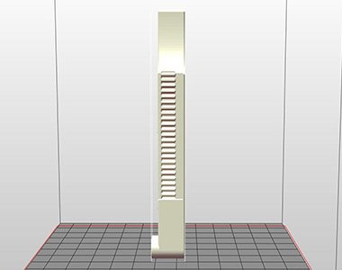
Due to tight requirements for smooth surfaces, there are a few options how to orient this part. The only reasonable solution is the riskiest one – to position it vertically. We oriented it so that the head is at the bottom. It is also possible to position it in the opposite direction, i.e. with the head facing upwards, but we have chosen first option as that will result in less support marks. Moreover, we always want to avoid obvious increase in cross-sectional area. That will happen if we orient head upwards as lower section is a bit curved.
Such vertical orientation is how you should not orient your parts regularly. Due to such orientation, cross-sectional area of each consequent layer will be almost the same as of the previous layers. This will put huge stress on previous layers and connections in between. In severe cases, with incorrect exposure times (i.e. cure times) layer delamination can happen. Then you would end up with partly separated layers in the middle of the part or it will break off entirely.
Supports
Due to selected orientation, there are not many surfaces that we will have to support for this linear gear.
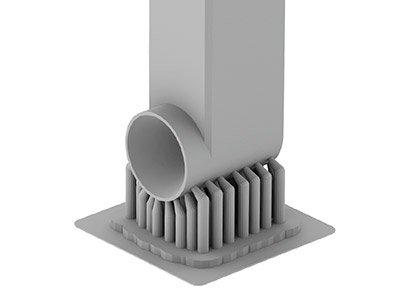
The only obvious reason why we need supports in this case is that we will have to place entire part on them. Because area at the bottom is very small, we will have to increase density of supports dramatically and set quite thick tip diameter (~0.5 mm).
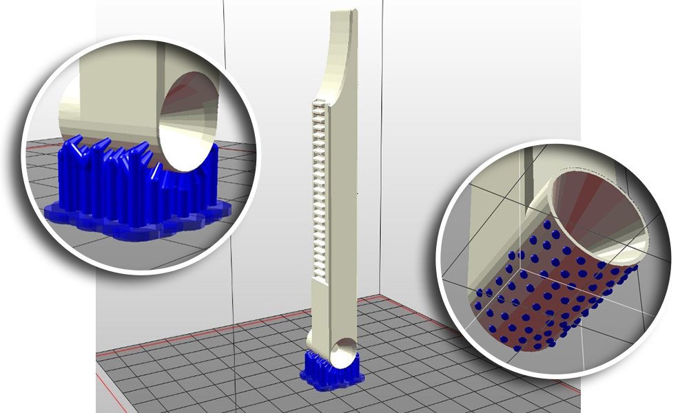
These supports and their tips will have to withstand layer separation forces from FEP for almost 2500 layers. That is the reason for such density and thick tips.
We also did not rely on automatic support generation because even at highest density settings software generates supports poorly. Therefore, we carefully position each support by hand and keep the balance across the entire area of interest. Considering that build time will be long and risks are high, we place extra support for each point where we usually would not place one. However, no matter how many of supports we place, their removal should not be complicated as it will be possible to cut all of them in one go.
Hollowing
In order to receive optimal results hollowing is especially important aspect. This linear gear has a thickness of around 12.5 mm, so hollowing is a mandatory step for success with SLA 3D printing.
Autodesk Meshmixer was used to hollow the part. We set thickness of wall to 2 mm and carefully placed some drainage holes in order not to disturb vertical movement during actual usage. Radius of holes was around 1.5 mm. We usually like to use wider holes as we use syringes with IPA to clean internal sections of the part.
It is also worth mentioning that we did hollowing after supports on purpose. If you hollow the model and then move to supports step, automatic generation functions tend to place supports inside the part. It is impossible to remove them, and internal supports could cause some issues especially if you decided to print with clear materials.
Attachment layer / Raft
Based on our recommendation covered in previous article we have added attachment layer for this part. Supports that were used for this linear gear have thick and even base. Due to this reason, if there was no attachment layer for this part, separation forces from FEP film or PDMS of bottom layers would put huge stress on very first layer that is attached to the build plate of the printer. Therefore, the likelihood of SLA 3D printed gear falling from the build plate would be extremely high. Attachment layer will help to increase adhesion forces between the base of this linear gear and build plate.
3D Printing
We 3D printed this gear on Anycubic Photon SLA (MSLA) 3D printer. Layer height was set to 50 um and slicer produced 2458 layers. Exposure time for a single normal layer was 6 seconds. We cured base layers for 120 seconds.
Although, we used Anycubic Photon 3D printer, this gear can be easily printed with any kind of SLA, LED or DLP 3D printer such as Wanhao D7, Phrozen Shuffle, Prusa SL1, Peopoly Moai, Dazz 3D, Uniz Slash, Zortrax Inkspire, Flyingbear Shine, Sparkmaker, Kudo3D Bean etc. You just have to select the correct layer exposure times.
Post-processing
There are no special post-processing procedures for this SLA 3D printed linear gear. After printing, we removed it from the build plate, cleaned it with IPA: left it submerged for 10 minutes and then swirled around a bit. Because supports were quite thick, we delicately removed them with a pair of pliers. We did this before post-curing as we do not expect it to experience serious warpage while in UV oven due to material properties. Sometimes it is good to leave supports while post-curing in UV oven to prevent severe warpage as supports would help to preserve structural integrity of the object. We post–cured this linear gear in UV oven (50W of 395nm LEDs) for ~2 hours.
Final results of SLA 3D printed gear
Below you can see fully finished 3D printed object. All requirements are satisfied. It was tested it and it works perfectly, i.e. measures extension with an accuracy of 50 um.

We would like to emphasize that there are different ways to 3D print this linear gear: one may choose different supports strategy or orientation etc. Each of us might have unique experience and personal preferences. So, if you wish to share your own insights, just send us an email, we will be happy to discuss it. We are constantly learning as well.
Related Posts:
- Rapid Prototyping 3D Printing – Wondering how this gear came together fast? This walks you through it.
- 3D Design Parts SLA 3D Printing – Want to design stuff like this? Here’s how to make it happen.
- Resin 3D Printing Troubleshooting: A Comprehensive Guide – Resin 3D prints flopping? This fixes what’s going wrong.
- Resin Mechanical Properties – Curious what resin is the best for your project? This lays it out.
- Key Things to Know Before Calibrating Resin 3D Printer – Need precision like this? This helps you calibrate right.
Digging this gear? Check our shop for resins that’ll fix your prototyping hassles!