Updated on July 26, 2018
Many of us have seen our resin print warping or even cracking some time after it was printed. Quite often you can solve this by implementing proper model design techniques. In this article we will cover key 3D design elements of SLA 3D printed parts. It is dedicated to experienced users who are already familiar with SLA 3D printing basics and are capable of designing their own parts.
In order to successfully print your own custom designed parts you must learn the fundamental design concepts of 3D printed parts. As a matter of fact, there is no specific and extensive guide on how to 3D design parts for SLA 3D printing. However, some conventional manufacturing techniques already possess some proven methodologies and knowledge. Therefore, in this article we would like to merge currently exploited manufacturing techniques and AmeraLabs experience in resin 3D printing. We believe this will help you get an understanding on how to approach delicate design problems of DLP/SLA 3D printing parts.
This article should not be treated as a step-by-step tutorial. It is more like a reference and can be used as needed.
SLA 3D printing resin and photo-polymerization reaction
Resin 3D printing uses photopolymer UV resin that harden under UV light. This so called “hardening” is technically called “cross-linking” of material, when it is transformed from liquid state to solid. This reaction is exothermic. This means that during transition a lot of heat is produced. Sometimes temperatures can reach more than 100 °C (212 °F) and can easily burn your skin. Moreover, the process of “cross-linking” causes unwanted shrinkage and if your part is poorly designed, it can even cause warping of your resin print.
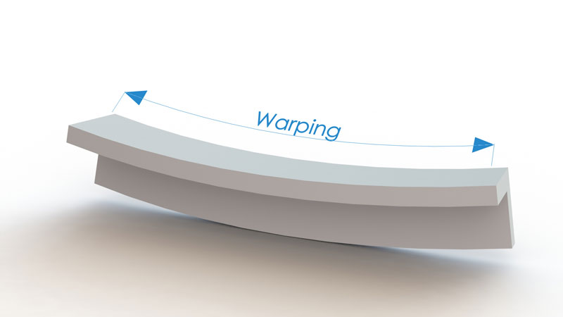
It is also worth mentioning that not all resin is cured right after 3D printing process. Although, we have solid object there is still uncured resin within the 3D printed part. This uncured resin continues to cure in the presence of ambient UV light that is all around us. Ongoing curing can still cause cracks and warping, which can be reduced if proper resin 3D print design techniques are used.
So let’s discuss some key design concepts that will help you to overcome these obstacles.
Walls
Wall thickness
It is well known that it is practically impossible to print large, solid, non-hollowed objects with resin 3D printers. The thicker wall is, the higher stress is put on your 3D printed object. This stress will eventually cause major surface and internal cracks. Moreover, if one uses bottom-up style SLA 3D printer with FEP/PDMS resin tray, large cross-sectional area will also lead to great layer separation forces from FEP or PDMS.
Therefore, hollowed objects with quite thin walls are preferred. Thinner parts also weigh less and use less resin per 3D printed object. This becomes very important for bottom-up SLA 3D printing machines, where object is hanging upside down and is constantly affected by gravitational forces. On average, the wall thickness should range from 1 mm to 2 mm (.080 inches to .160 inches). It is possible to go for a bit thicker walls, but that must be tuned up with overall design. Also you should select proper 3D printing resin with low shrinkage profile. You can also use thinner walls, but when removing supports, increased fragility can cause issues.
Uniform walls
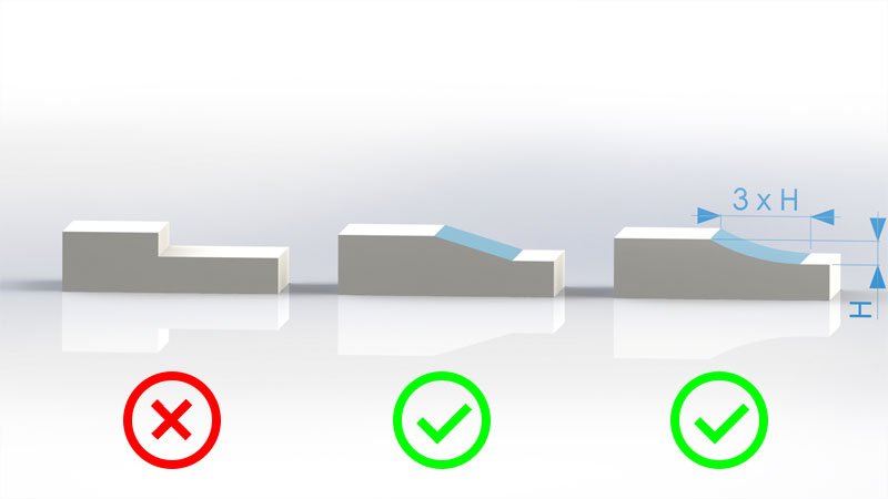
We strongly recommend keeping your walls consistent and uniform. If the walls of DLP 3D printed object are not uniform, the thin sections that consist of less material will shrink less. Those thin segments will also stop shrinking sooner than thicker ones with more material will. As the thick section yields, it leads to warping of the resin print that eventually causes cracks, because thin segments simply do not yield anymore.
What if you cannot have uniform walls due to design limitations?
Sometimes it is impossible to have uniform wall thickness. In such cases, change of wall thickness must be as uniform as possible. By following this principle, stress and risk of potential cracks will be reduced. See images below on how very simple formula for wall thickness transition can be exploited.
Bosses
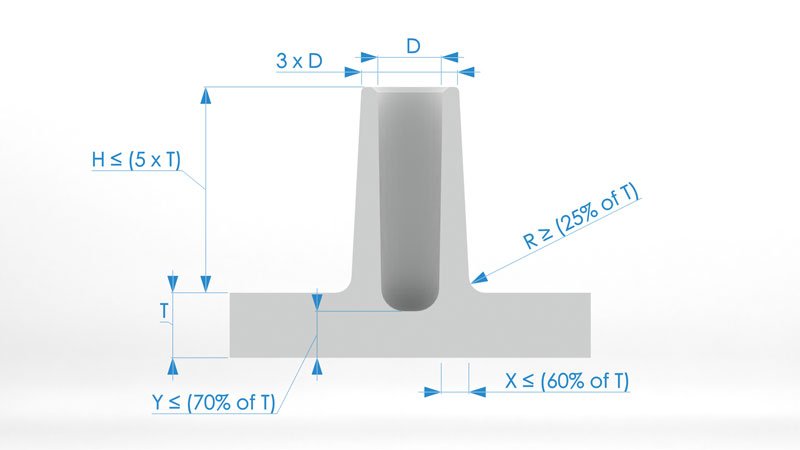
The most common purpose of bosses in design process is to facilitate parts mating. Typically we use it for attaching fasteners such as screws. However, we strongly recommend to print test parts with your tapping drill sizes separately and see how they work before printing full design. The reason is that resin 3D printing materials end up being quite brittle and tapping becomes even more complicated. Usually any tapping efforts will result in cracks and damaged parts. Therefore, by printing test parts and experimenting, you will be able to avoid problems when tapping your final part. Below we present guidelines for boss design.
Ribs
Generally ribs are used to increase the bending stiffness of designed part without adding any additional thickness. Ribs increase the moment of inertia that increases the bending stiffness and reduces warping of resin print.
Bending Stiffness = E (Young’ s Modulus) x I (Moment of Inertia)
Rib thickness should be lower than wall thickness to minimize risk of potential cracks and additional stresses after 3D printing and during post-curing. We suggest to aim for 60% of the wall thickness. Also it is important that rib would be attached with corner radius as softly as possible. Draft (wider base) for a rib is not mandatory, but in some cases, reducing the angle at which it is 3D printed might be helpful. This can help to reduce the need of additional supports. See guidelines for rib design in the image below.
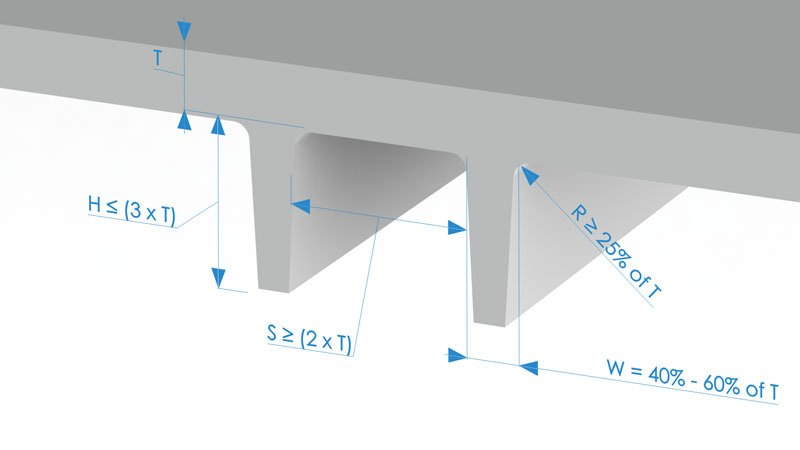
Moreover, there is one more important facet to consider if you have part that has intersecting ribs. These intersecting areas will have greater thickness and, thus, more material. You can easily remove excessive material by simply hollowing the intersection of ribs to preserve uniform wall thickness and material volume.

Gussets
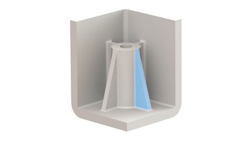
So called gussets is another technique to increase stiffness of 3D printed structure. These are support structures that can be designed to minimize warping of the part. In general gussets may be considered a subset of ribs and the guidelines for ribs also apply to gussets.
If gusset is attached to the boss, its height can be 95% of that boss. However, its height should be less than 4 times the nominal wall thickness and the preferred height is 2 times the nominal wall. When it comes to the length of the gusset, it can vary from 30 % to 100 % of the height of the gusset.
Sharp corners
Quite sharp corners can vastly increase concentration of stress for your resin 3D printed parts. This stress can lead to severe cracks and, in extreme cases, to total 3D printed part failure. The radius of sharp corners has to be closely taken care off, because the stress concentration varies with radius for a given thickness.
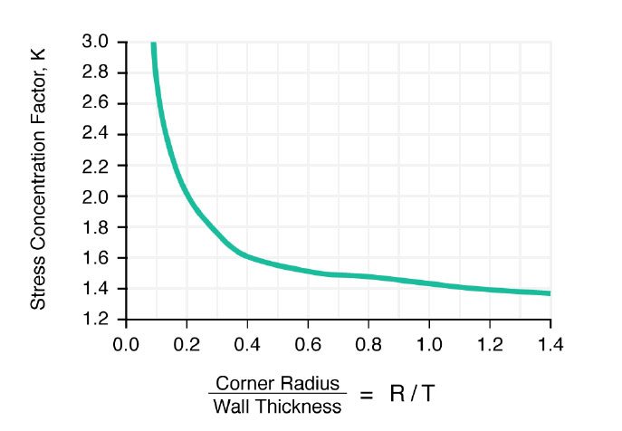
As it is visible in the chart, stress concentration factor is high for R/T values less than 0.5, but lowers for R/T values over 0.5 concentration. The stress concentration factor is a multiplier that greatly increases stress. Therefore, we strongly recommend to make inside radius a minimum of one time the thickness.
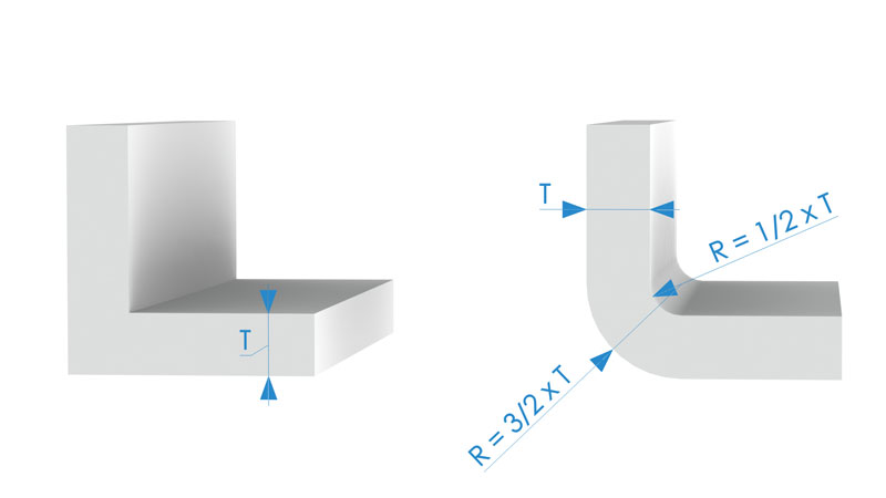
At corners the suggested inside radius is 0.5 times the material thickness and the outside radius is 1.5 times the materials thickness. If your SLA 3D printed part design allows it, it is strongly recommend to use bigger radius.
Example project of resin print warping
We would like to demonstrate, how proper design techniques can affect your resin 3D printing results. Therefore, for this task we will conduct an experiment of 3D printing a case for a circuit board.
To better illustrate design effects on 3D printing success, we made two 3D designs of the same case: one without design guidelines and second one with design guidelines implemented.

Key 3D design elements
- Both cases are 90 mm x 50 mm x 16.5 mm.
- Proper design kept all walls uniform at 1.5 mm in thickness.
- Incorrect design also had walls of 1.5 mm as we thought that final judgement might be too ambiguous if the wall thickness differs too much. Height of the walls of both designs were 15 mm.
- Proper design had segments of thicker walls and those were smoothly transitioned to thinner walls.
- Incorrect design also had thicker walls, but no smooth transitions were made.
- Proper design used ribs to strengthen bottom part of the case and to reduce resin print warping and shrinkage. Ribs were 2 times higher than wall thickness. Areas where ribs are attached to walls were rounded to reduce stress.
- Incorrect design did not use ribs at all.
- Proper design also incorporated gussets to improve strength of walls even more since box will be 3D printed at an angle. Dimensions of gussets: 3 mm base, 10 mm height and 0.9 mm thickness.
- Incorrect design did not use gussets at all.
- Proper design had all sharp corners rounded according to guidelines we presented in the sections above. Inner radius for fillets of all corners was 0.75 mm and 2.25 mm for all outer fillets.
- Incorrect design was kept with sharp corners.
- Proper design had holes for threads moved to separate bosses and strengthened using gussets and ribs. Ribs were as high as boss with thickness of 0.9 mm and gussets had the same dimensions as those used for walls.
- Incorrect design had thread holes incorporated into walls.
3D printing parameters
- DLP 3D printer with Acer H6510BD projector (similar to Kudo 3D Titan 1 and Titan 2).
- Normal layer exposure time – 4 seconds.
- Bottom layers exposure time – 50 seconds.
- XY resolution – 55 um.
- Layer height – 100 um.
- Normal layers lift speed – 40 mm/min.
- Bottom layers lift speed – 10 mm/min.
- All boxes were post-cured while still on build plate and with supports for 2 hours. Additional post-cure of 1 hour was done after supports were removed.
- AmeraLabs special blend material was used.
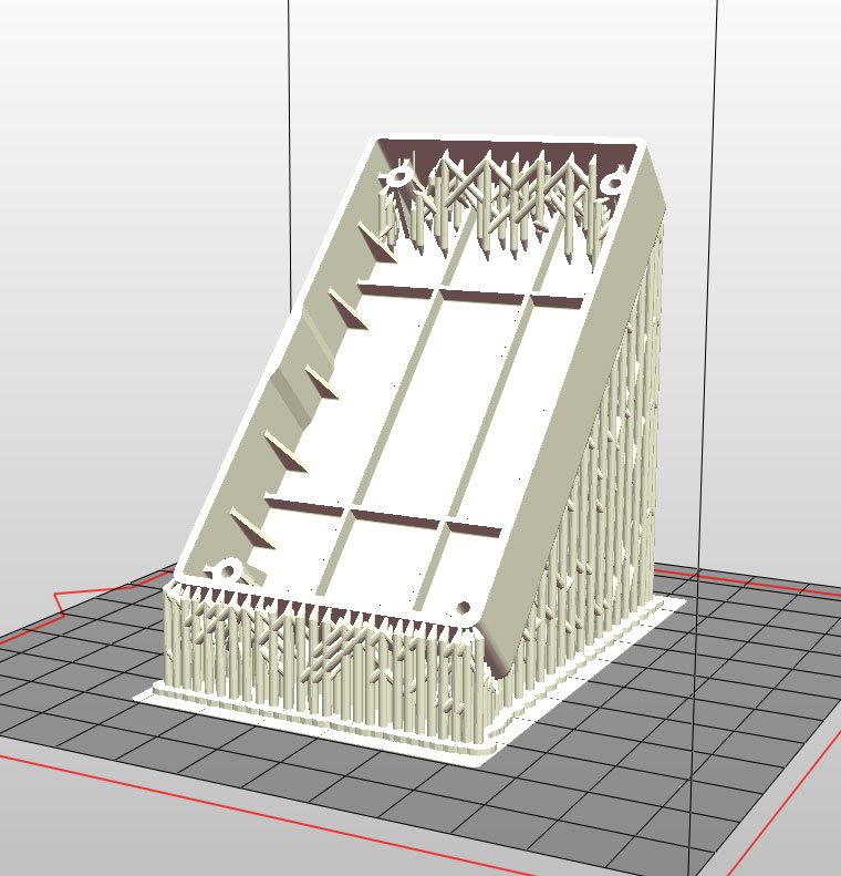
It is important to say that serious warpage in SLA 3D printing actually happens during 3D printing process. With bottom-up style machines like Anycubic Photon, Wanhao D7, Peopoly Moai or most DIY SLA 3D printers that use FEP of PDMS coatings for resin trays, cured layer separation action puts a lot of stress on the part. Final result highly depends on proper support techniques that must be used to reduce resin print warping during 3D printing. After you are successful with 3D printing process, good design implementations come into play. These will help to sustain structure and shape of the object in the long run when exposed to ambient UV light.
Final results – resin print warping
After we printed, cleaned and post-cured all cases, we placed them outside on a window sill. We investigated final results after two weeks. Below, we present images for your judgement and evaluation.
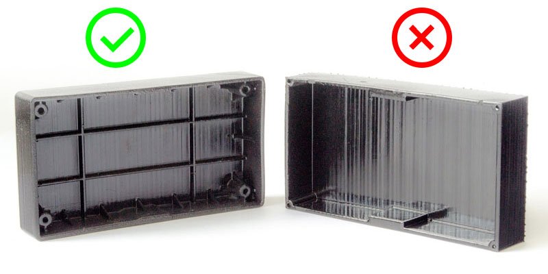
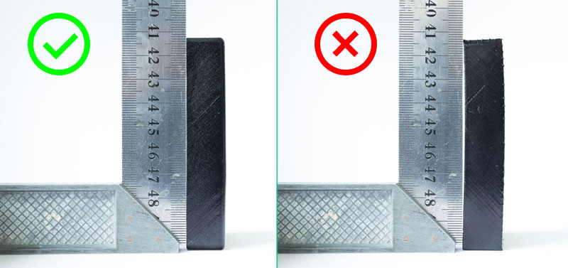
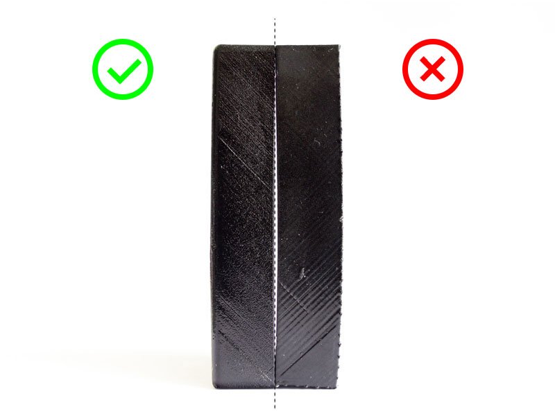
After this thorough investigation of cases it was quite clear that design guidelines helped obtain better results. We observed less warping on resin print designed by following these guidelines. Moreover, even after two weeks the print managed to preserve almost flat surfaces. On the other hand, although, we saw no cracks on the incorrect 3D design, this case suffered greater warpage and deformations. Since both cases are quite small, differences might look intricate, but because we all want to be as precise with SLA 3D printing as possible, everything counts here.
What’s next?
We hope, that you have learned some of the key principles needed to design functional prototypes. Now go and put them into practice. If you need some resin for prototyping, we’ve got you covered – check out our engineering resins.
Other articles from AmeraLabs
- Case Study: 3D printed Linear Gear for Extensometer
- 6 Key Principles of 3D Printing Supports that Work
- Attachment Layer in SLA 3D printing: what you need to know
- Key things to know before calibrating resin 3D printer
- Experiment: outdoor environment effect on resin 3D printed parts
- 10 reasons why you get unexpected horizontal lines on your 3D printed parts
